
Adaptive Optics Module
Introduction
The Adaptive Optics module of Telescopio
Nazionale Galileo (AdOpt@TNG) is permanently mounted at the
Nasmyth A
interface and provides two distinct kinds of correction: the
tip-tilt (T/T) and high orders (HO) corrections. Both kinds of corrections have already
been implemented at first light. At the moment only the T/T compensation is available for
observations while the HO correction needs to be further optimized and its availability is
foreseen during 2001.
Into the AdOpt module also a Speckle facility is implemented.
Take a look at this
page if you would like to observe at the TNG with the T/T correction or with the
Speckle camera.
 |
| Fig. 1. Scheme of the Adaptive Optics Module |
Image correction
A pick-up mirror folds the light beam
coming from M3 into the optical train of the AdOpt module where a first off-axis parabola
reimages the pupil onto the Deformable Mirror (DM in Fig.1).
The off-axis parabola is also the T/T mirror compensating
the centroid motion of the image due to the low spatial frequencies component of the
atmospheric turbulence. The T/T device has four voice-coil actuators whose stroke is
controlled through capacitance sensors used in a differential mode to drive the control
loop and giving, in this way, a great accuracy in the mirror positioning measurements.
There is also a dummy mass to counter-balance the angular momentum of the device.
The bandpass of the T/T mirror is about 1.5KHz and, on the average, the actuation delay
time is 1.35ms.
The DM is the mirror for the HO compensation. It is a continuous facesheet mirror with 97 magnetostrictive actuators; it reflects the beam to a second off-axis parabola which forms the image on the detector focal plane.
This optical train gives a global focal
ratio of F/32.2 and does not affect the image quality of the telescope even for
diffraction limited images over a field of view of 1x1 arcmin in the near IR (J, H, K)
and of 30x30 arcsec in the visible (V, R). The light is sent directly to the
NIR imager or, by inserting a
flat folding mirror, to the optical imager
(OIG): the number of total
reflections after M3 are 4 in the IR and 5 in the visible. All the mirrors have a silver
protected coating with a reflectivity of at least 95% in the visible and 98% in the IR.
Wavefront sensing
The beam to the wavefront sensing area is collected after the second off-axis parabola through a four positions wheel with a set of dichroic filters. The spectral responsivity of the dichroics can be chosen between respectively Tx = 50% and Rx = 50% of the light in the range between 0.45 µm and 2.2 &micero;m, then Tx = 90% and Rx = 10% in the same spectral range and finally Tx = 100% for the IR light (approximately from 0.9 µm) and Rx = 100% for the visible spectrum to the WFS; the fourth position of the wheel is empty for the speckle camera and for using the AdOpt optical train as a simple focal extender for the two imagers.
Two kinds of T/T sensors can be used.
- The APD T/T sensor has an optical image dissector splitting at F/200 the light of the guide star into four beams towards four avalanche photo diodes (APD). Using the difference between the APDs' signals the centroid position of the star is retrieved and the correction through the T/T mirror is applied. The APDs have a maximum sensitivity at 0.7 µm with a quantum efficiency peak of 65% and a passband of 220nm.
- The pyramidic wavefront sensor can be used both for the T/T only correction and for the HO correction. The guide star is focused on the vertex of a pyramid with 13 µm roughness on the edges and a 174° vertex angle. The pyramid (which can be vibrated up to 100Hz with 250 µm Peak to Valley amplitude) together with a reimaging optics produces four pupil images onto a four quadrants read-out 80x80pixels EEV39 CCD.
A fast CCD controller allows for up to 400Hz frame rate with only 7 electron rms Read Out Noise.
The wavefront computer is a real-time matrix multiplier
able to evaluate slopes from pixels intensities and to multiply current and past measured
slopes with a user provided matrix. Latency time of the wavefront computer is less than
260µs.
A nutating mirror just before the wavefront sensing area allows for off-axis corrections and to maintain the guide star in the sensor field of view in case of targets with proper motion such as asteroids.
Tip-Tilt performances
Only The Tip-Tilt correction is fully operating at the TNG Nasmyth A focus and serves the IR imager.
The Tip-Tilt system needs a guide star to sense the jitter induced by the atmosphere in order to apply an efficient correction. The sharper and the brighter is the guide star the better is the correction. It becomes mandatory to have in the neighbourhoods of the astronomical target a source satisfying these requirements. The guide star could be the target itself (the best situation) or a star bright enough located within 30" from the center of the field: in these cases a correction getting worse with the angular distance is expected. We recommend to not exceed the limit of 30" and to consider only guide stars brighter in V or R than Mag=13.
The larger is the observational wavelength the better is the correction under the same seeing conditions. Good performances are expected for K and K' bands, discrete for H band, poor for J. At shorter wavelengths it is also foreseen a small improvement of resolution mainly due to telescope tracking errors compensation, if any.
The better is the seeing the better is the correction: depending on the observational wavelength, there is a limit over which any correction is useless. This limit is more relaxed in K and K' and it becomes severe as the wavelength decreases.
Some particular atmospheric conditions could change the correction performances of the Tip-Tilt system such as variations of the isokinetic angle that depends on the vertical distribution of the atmospheric turbulence (see explanation).
In the three graphs shown here (referring to K, H and J bands) the relation between the FWHM of the corrected star and of the R magnitude guide star for different seeing values is reported, in the particular case when the two objects coincide. In the K band a small correction is expected even in case of bad seeing conditions, while in the H band the limit decreases roughly to a seeing value of 1.0" (V Band) and in J band to 0.7" (V band).
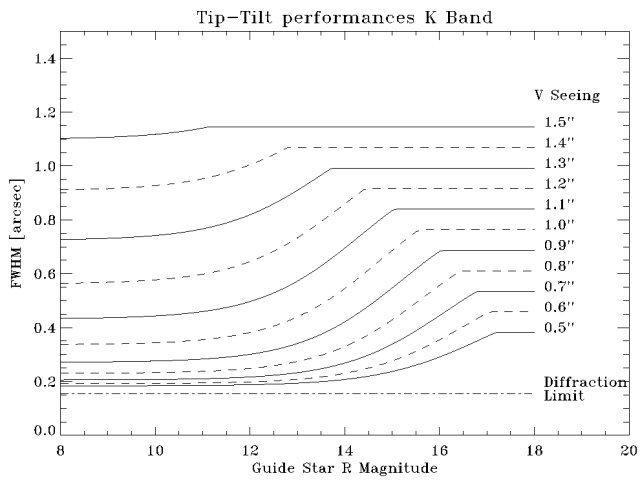
K |
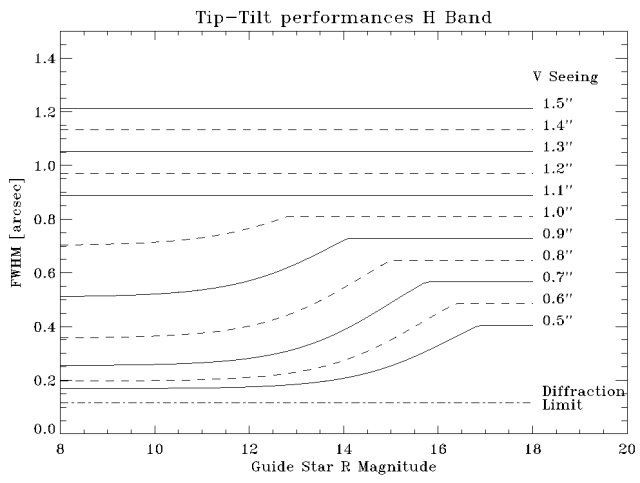
H |
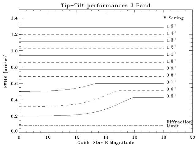
J |
The asymptotic values for dimmer magnitudes represent the natural FWHM due to the seeing at the corresponding wavelength. Even in K band the corrected FWHM never goes to the diffraction limit because a static blur of 0.1" due to the overall optical system (telescope+AdOpt+NICS) is introduced. The graphs are computed using a performance tool developed under IDL environment and the overall loop parameters used here are the same shown in the tool page. For the actual best experimental performances please see the latest news.
In order to help the future observer to understand the capabilties of the tip-tilt correction system, a simple performaces tool has been implemented.
For any comments please contact Massimo Cecconi.