
The Low Resolution Spectrograph
- Overview
- Imaging
- Long Slit Spectroscopy
- MOS Spectroscopy
- Flux standard data & Measured through-put
- Tool for Observations
- Polarimetric mode (Only photometric mode available)
- GRIS-U: a new grism available with DOLORES
- Imaging Flat Field Archive
Overview
DOLORES (Device Optimized
for the LOw RESolution), LRS
in short,
is a low resolution spectrograph and
camara permanently installed at the Nasmyth B focus of the Telescopio
Nazionale Galileo. Its design allows to perform imaging and low
resolution
spectoscopy observations. The instrument is based on a collimator and
on a focal reducer and camara. To select the observing mode GRISMS,
for the low resolution spectroscopy, or optical filters,
for multiband photometry can be inserted into the optical path soon
after the collimator.
Slits are carried by a slider, Tram
, located at the telescope focal plane. The Tram
can carry up to 5 long slits or Multi Object Spectroscopy (
MOS ) plates. Thanks to its design switching from imaging to
spectroscopy takes a short time ( about 2 minutes in the worst case ).
The camera is equipped with a 2048 x 2048 E2V 4240 Thinned
back-illuminated, deep-depleted, Astro-BB coated CCD with a pixel size
of 13.5 µ.
The Field of view is 8.6 x 8.6 arcmin with a 0.252
arcsec/pix scale.
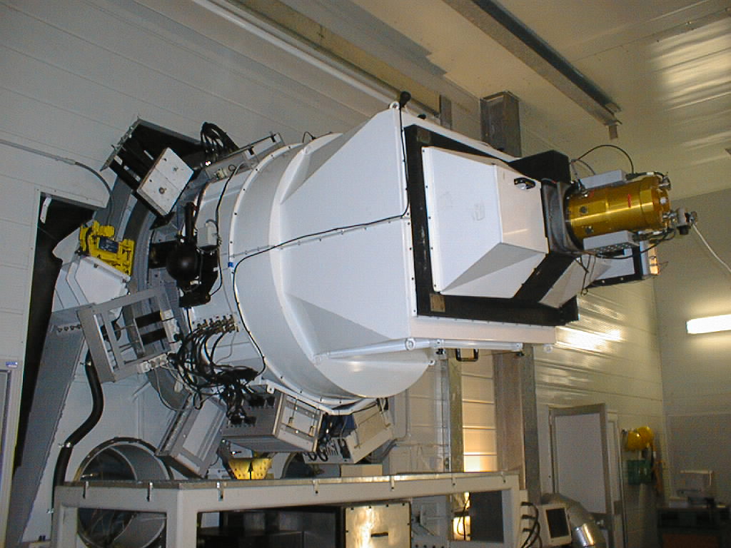
Figure 1. Picture of DOLORES mounted on the Nasmyth B focus.
The main parts of the instrument are (from the de-rotator outward):
- The Entrance Slider, which allows to
insert in the optical path one of the following calibration and
auxiliary systems:
- A calibration mirror for wavelength calibration with Thorium and Argon lamps.
- An off-board set of lamps (Helium, Neon and Halogen) for wavelength and Flat Field calibrations.
- A flat mirror which feeds the high resolution spectrograph SARG.
- The Tram which can carries 4 fixed width Long Slit Units (0.7", 1.0", 1.5", 2.0") or up to 4 MOS plates.
- The optical collimator
- The Filter Wheel. Normally eleven imaging filters are mounted on the wheel. ( please take a look at the TNG filters page for a list of available filters ).
- The Grism Wheel carries the dispersing optical elements ( grisms )and the focusing-pyramid device.
- The shutter
- The CCD camara
The CCD mounted since Januarry 2008 is an E2V technologies
CCD42-40 Astro Broadband, Deep Depleted. QE peaks at 95.8% around 600
nm and is 52.7% at 900 nm ( see Figure 2 and Table 1 ).
| Wavelenght (nm) |
QE % |
| 350 | 50.5 |
| 400 | 81.1 |
| 500 | 95.8 |
| 650 | 87.4 |
| 900 | 52.7 |
| 1000 | 13.3 |
Dark current is unappreciable even on long exposures and saturation occurs at ~65500 ADU. The full-frame readout time is 25 sec with binning 1x1 (default). Smaller windows and higher binning can be easily set to reduce the CCD read-out (see our CCD's Read-Out Time Calculator). Consider that, anyway, time between two consecutive images will not be less than the time taken to save the image on the hard disc plus the time taken to check the instrument setup.
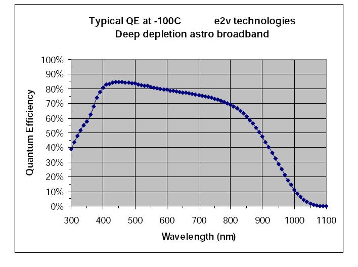
Figure 2. The typical E2V CCD Quantum Efficiency. Table 1 reports the
measured QE specified in the CCD data sheet.
Imaging
Normally, 11 imaging Filters are permanently mounted on the Filters Wheel.
The default Filters mounted on LRS are: U B V (Johnson), R I (Cousins), u' g' r' i' z' (Sloan) and the ~560 nm cut-on filter
Table 2 sums up instrumental Jhonson-Cousins zero points. The 'i' subscription stands for 'i'nstrumental, exposure time normalized and 0 airmass extrapolated magnitudes.
| Band |
mago |
| U-Ui | 24.0 |
| B-Bi | 26.4 |
| V-Vi | 26.2 |
| R-Ri | 26.3 |
| I-Ii | 26.0 |
Exposure times for the broad band UBVRI and u'g'r'i'z'
filters can be obtained with our Imaging
Exposure Calculator.
The La Palma extinctions coefficients and the Night Sky Brightness at
various lunar
phases are given here.
The E2V4240 CCD currently in use is characterized by an amazing low fringing level. See Fig.3
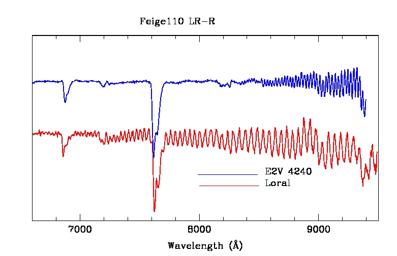
Figure3. In red the spectrum of the standard star Feige110 taken with the old LORAL CCD and the LR-R GRISM. In blue the same star taken with the E2v4240 CCD currently mounted and the same instrumental configuration. The significativelly lower fringing of the new CCD is evident.
LRS has a custom-made double-blade shutter which allows exposure times as low as 0.02s with uniform illumination of the Field.
HINTS for OBSERVATIONS:
Long Slit Spectroscopy
The LRS grisms wheel at present carries 9 Grisms and
the focusing
pyramid.
The grisms set was up-graded on October 2005 (see also our news
page.)
At present 7 of the 9 installed grisms are Volume Phase Holographic
grisms,
resulting in a substantial improvement of the spectroscopic
capabilities of the instrument.
The characteristics of the Dolores grisms are given in Table
1 (older table is available on this link).
The Exposure Times for the different grisms can be calculated using our Spectroscopy Exposure Calculator.
| Name |
disp. [Å/px] |
λmin
[Å] |
λc
[Å] |
λmax
[Å] |
Rc (1") (4)
|
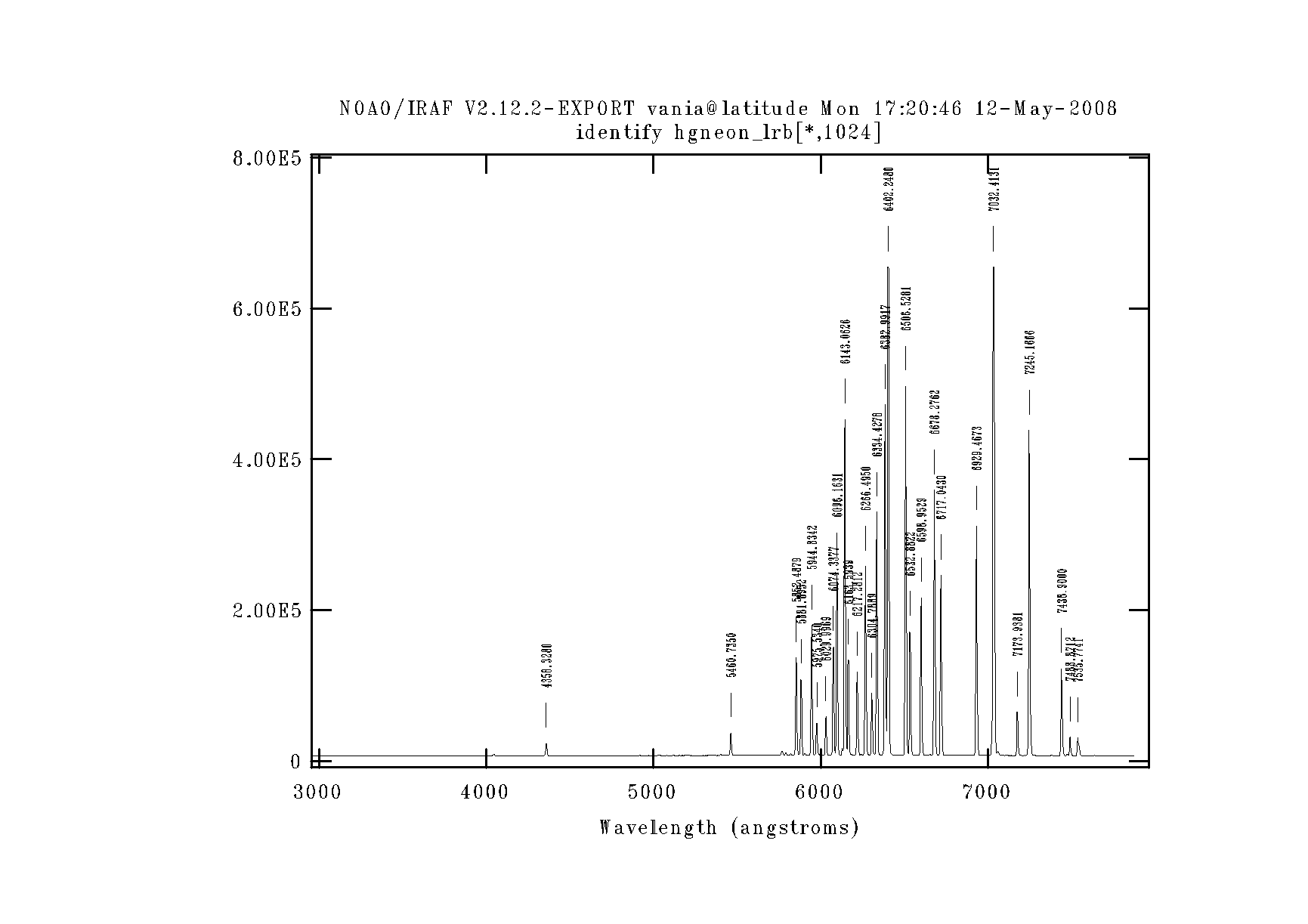
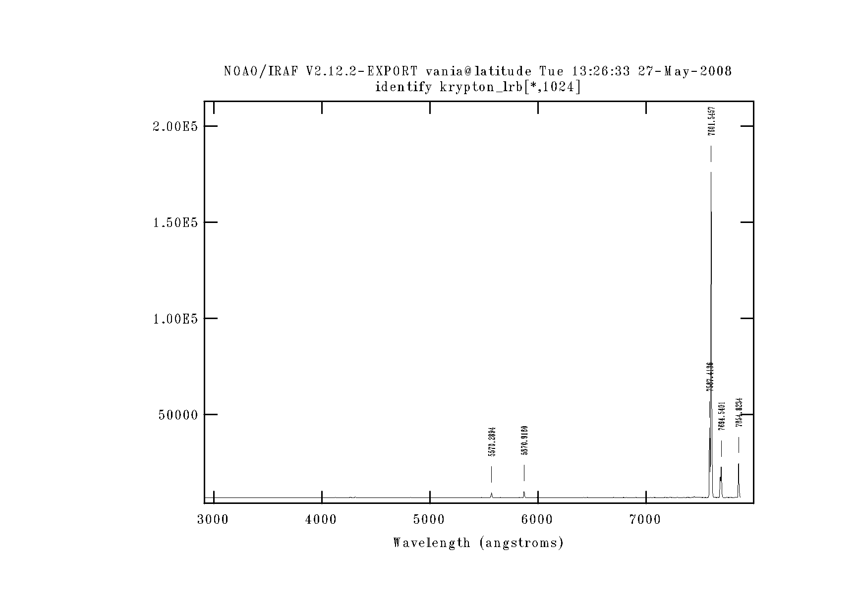
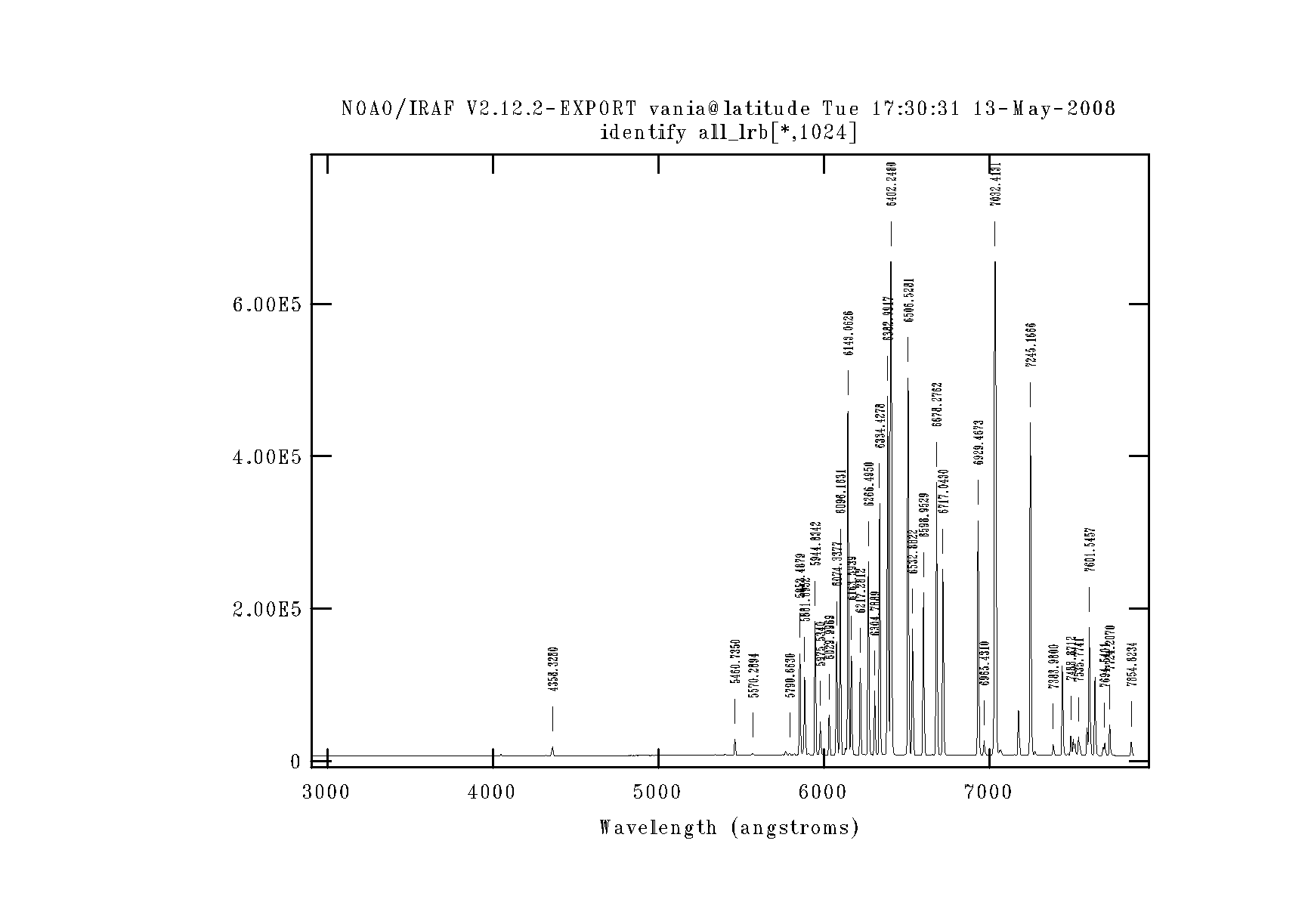
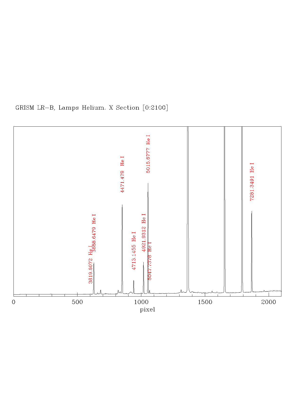
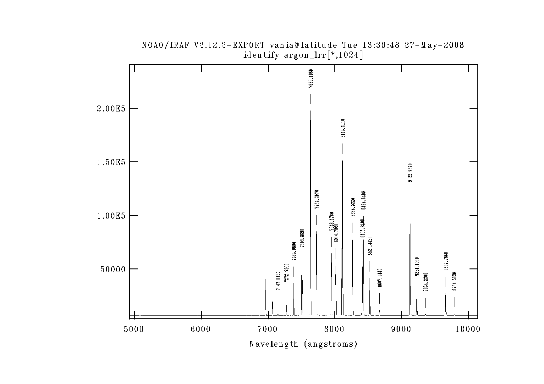
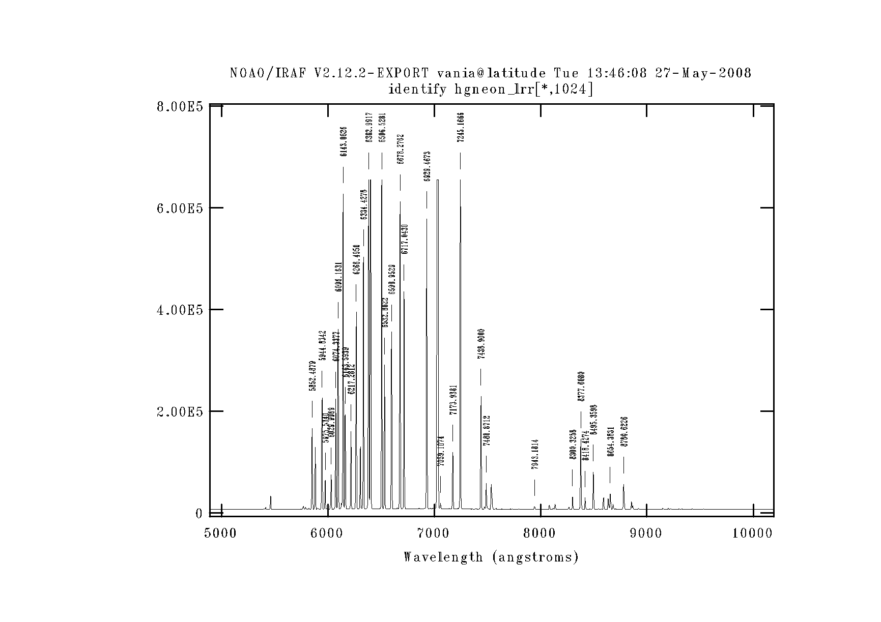
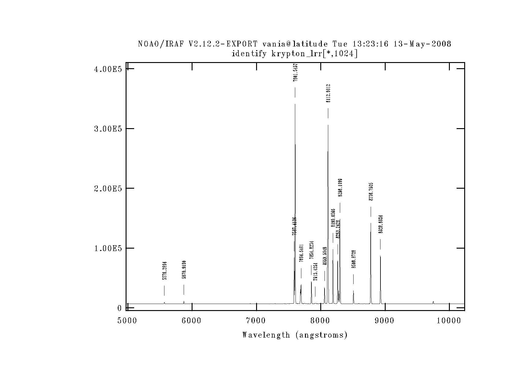
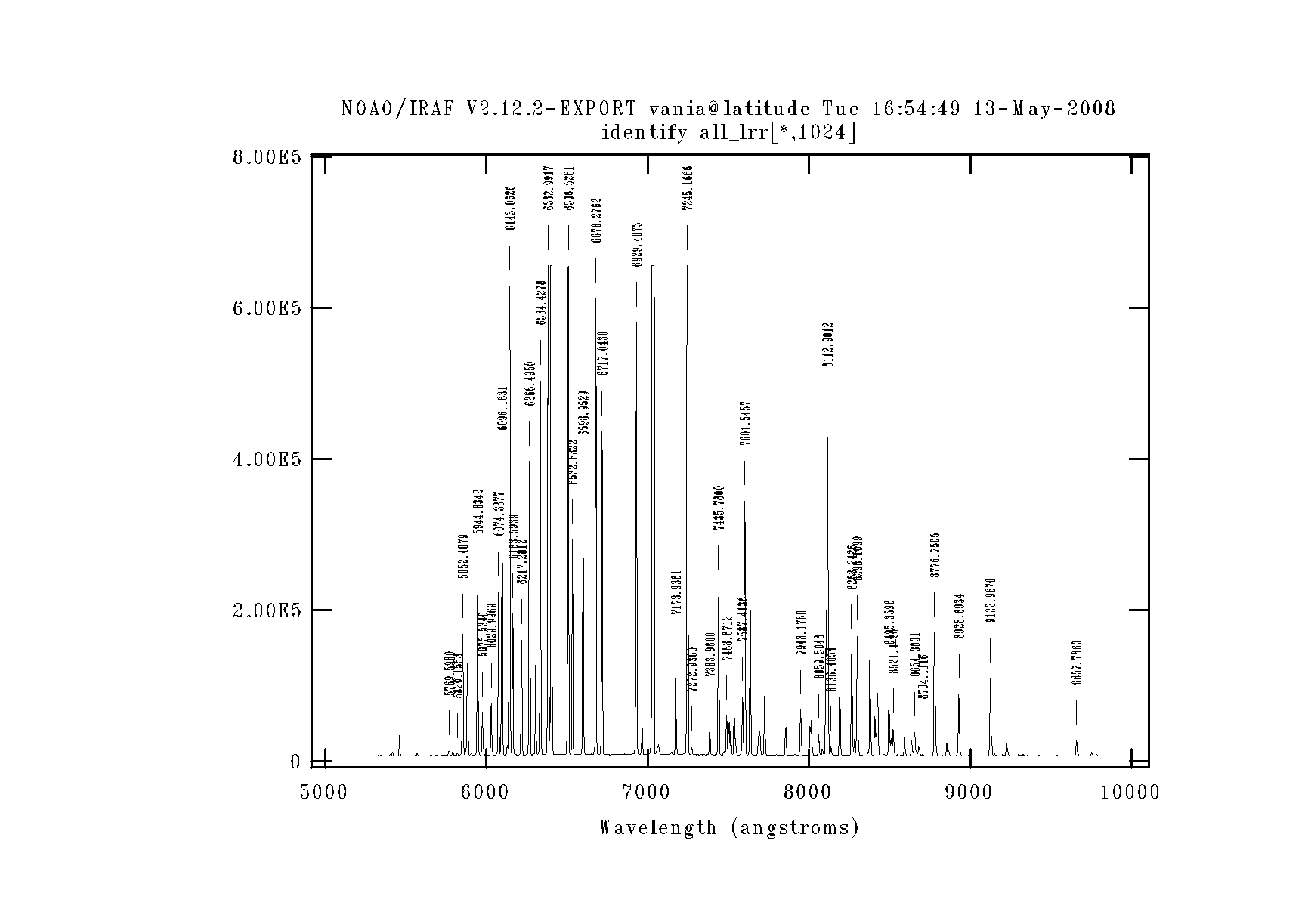
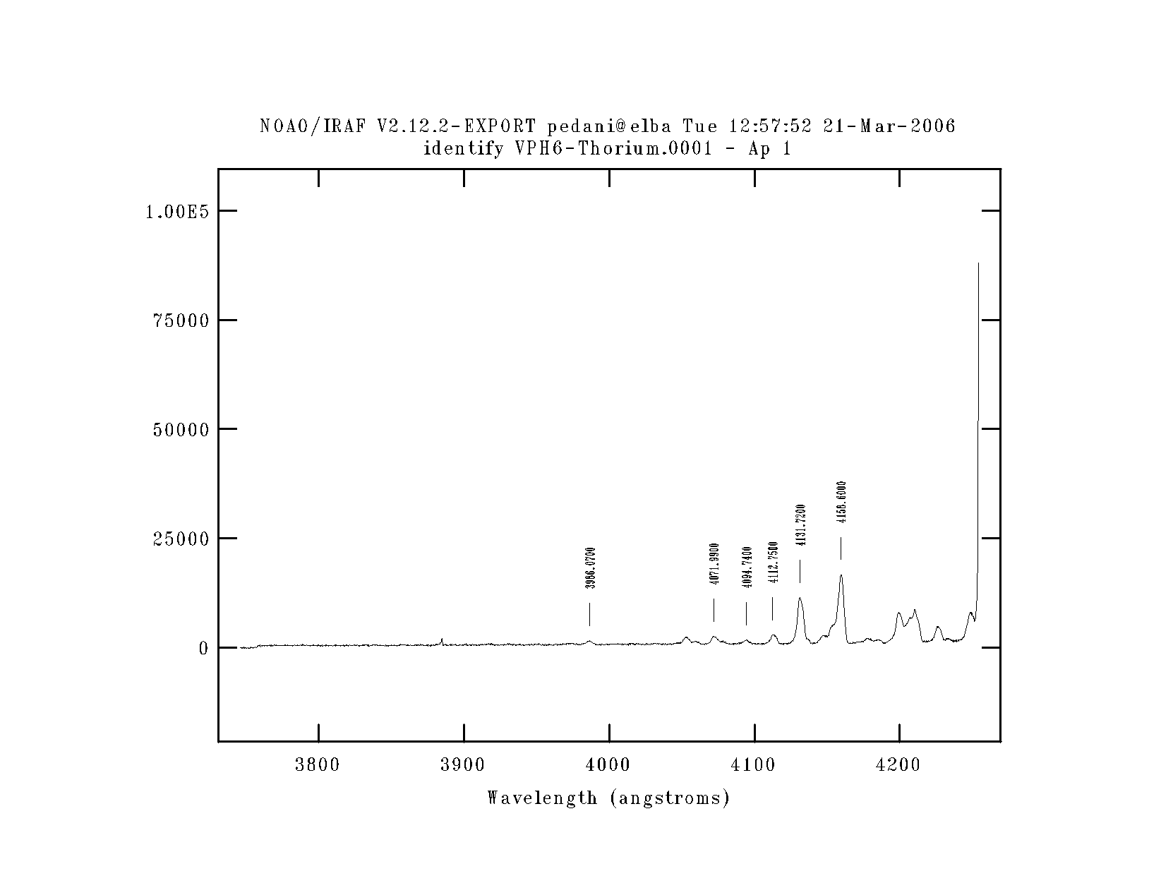
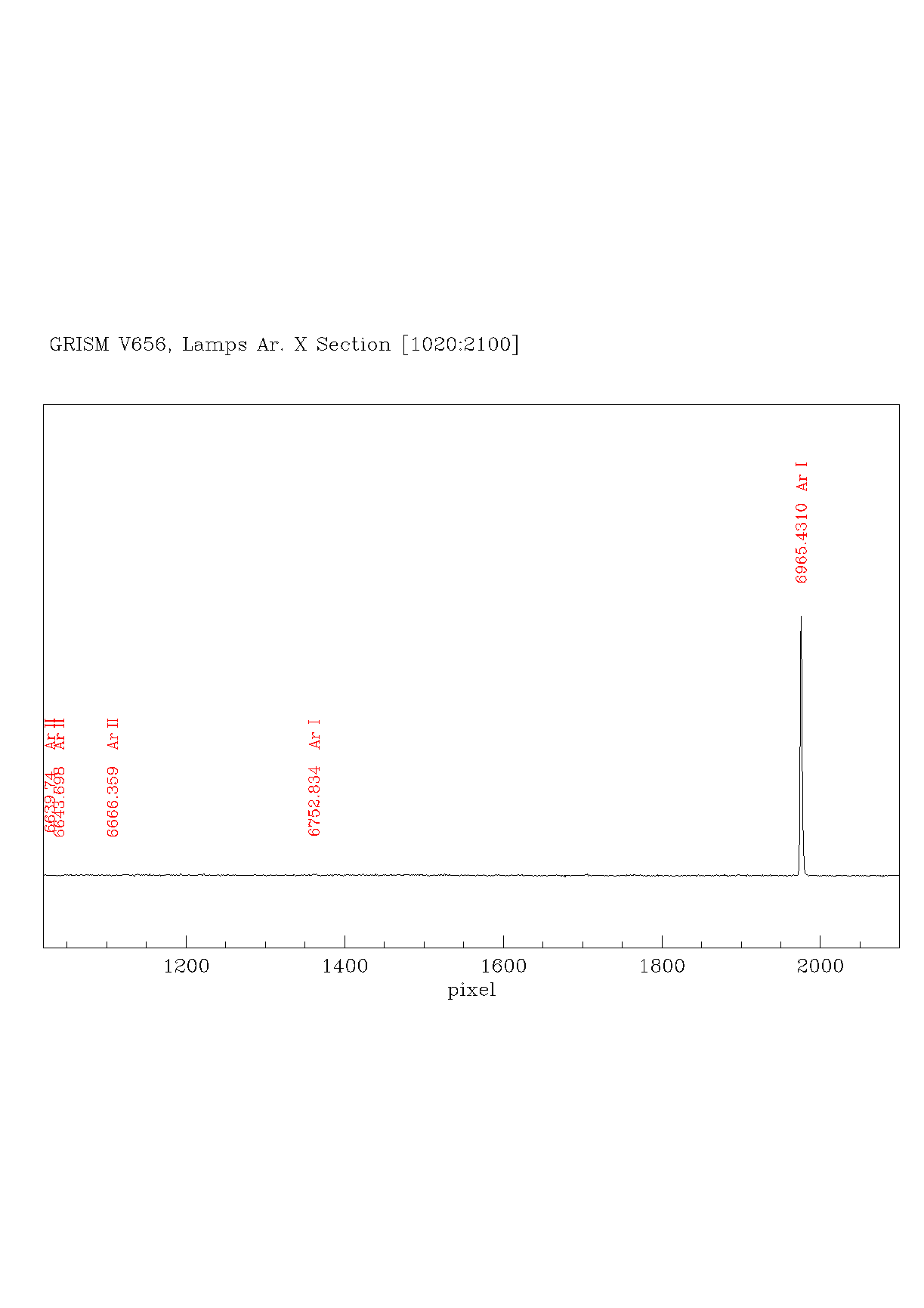
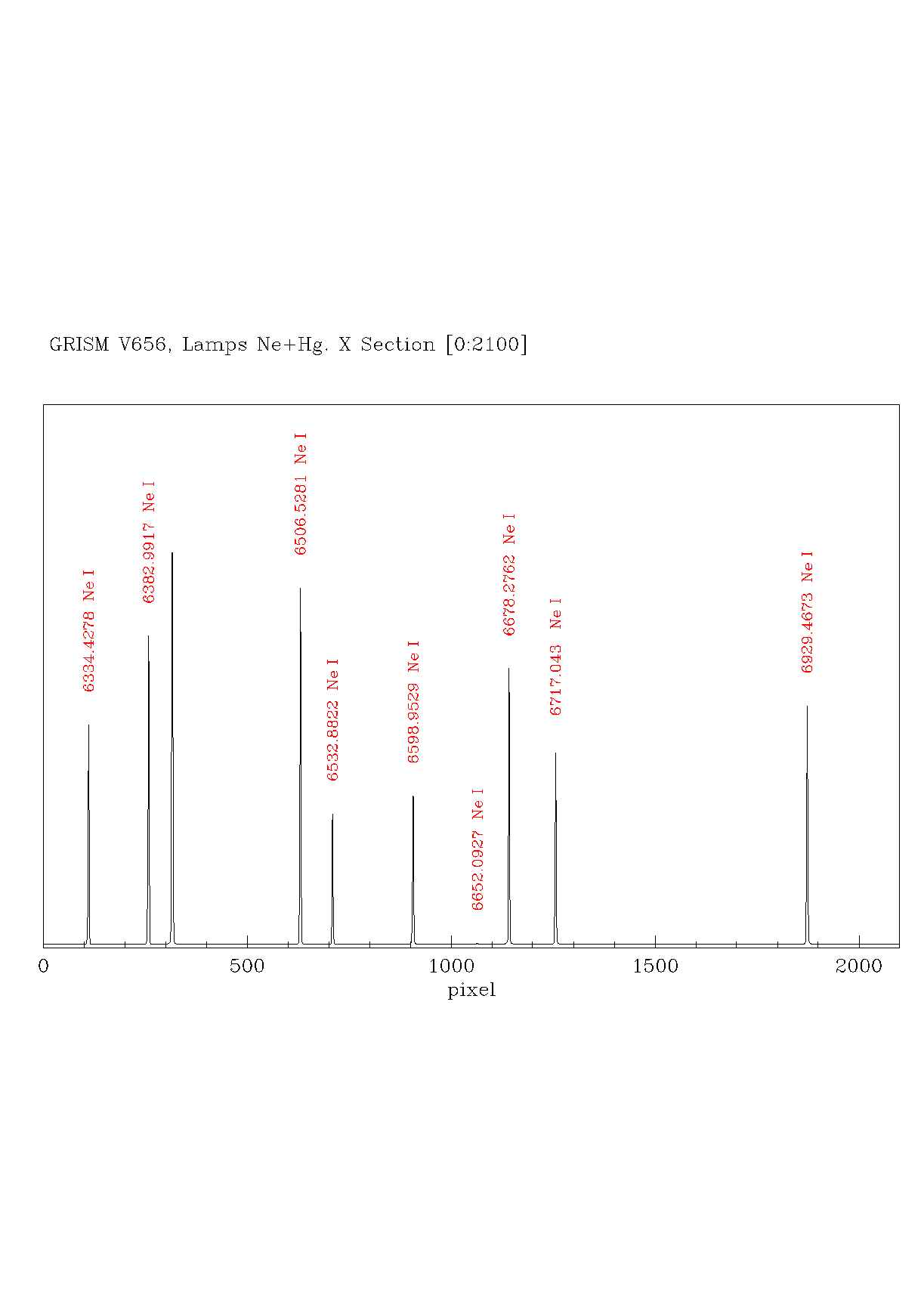
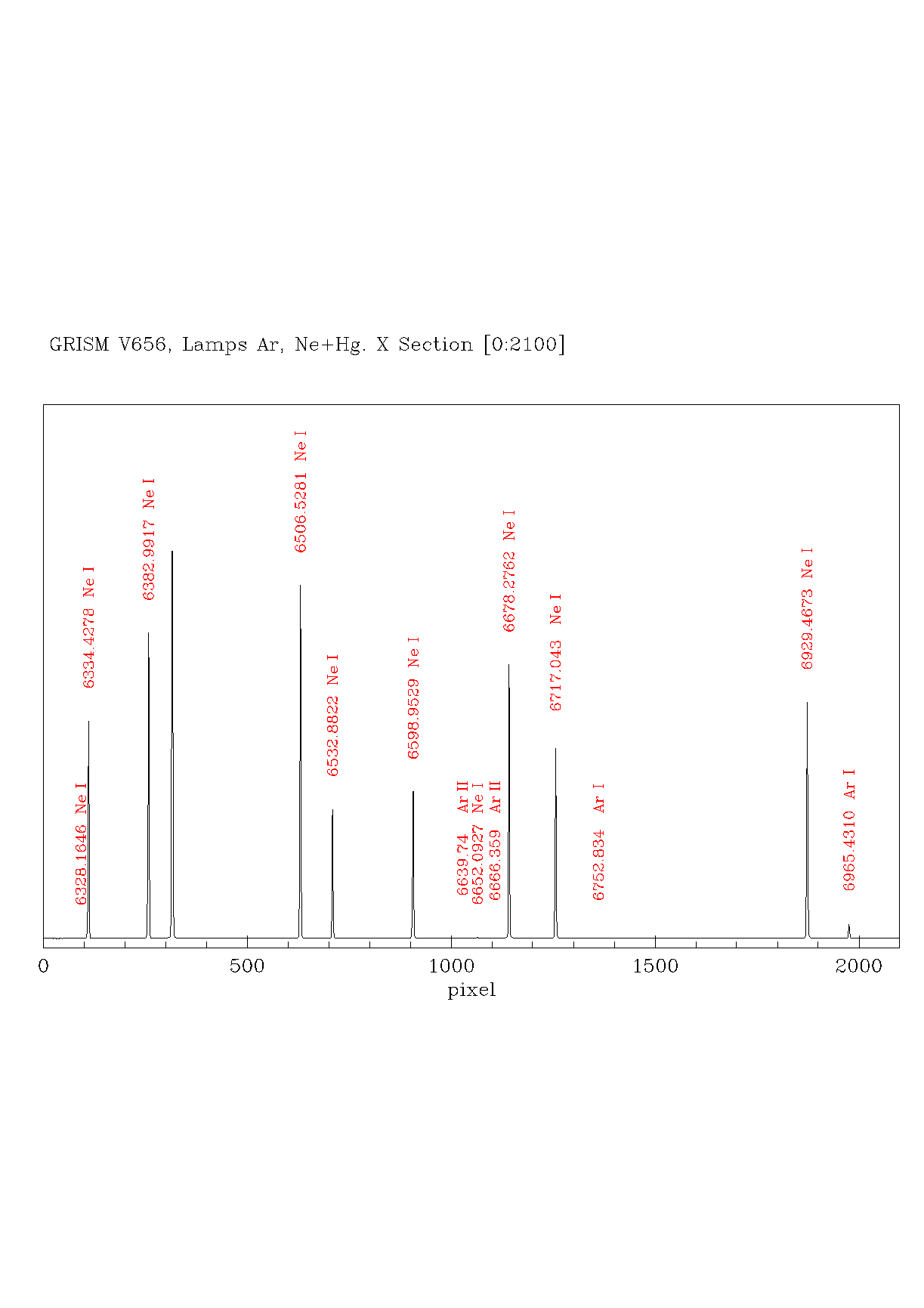
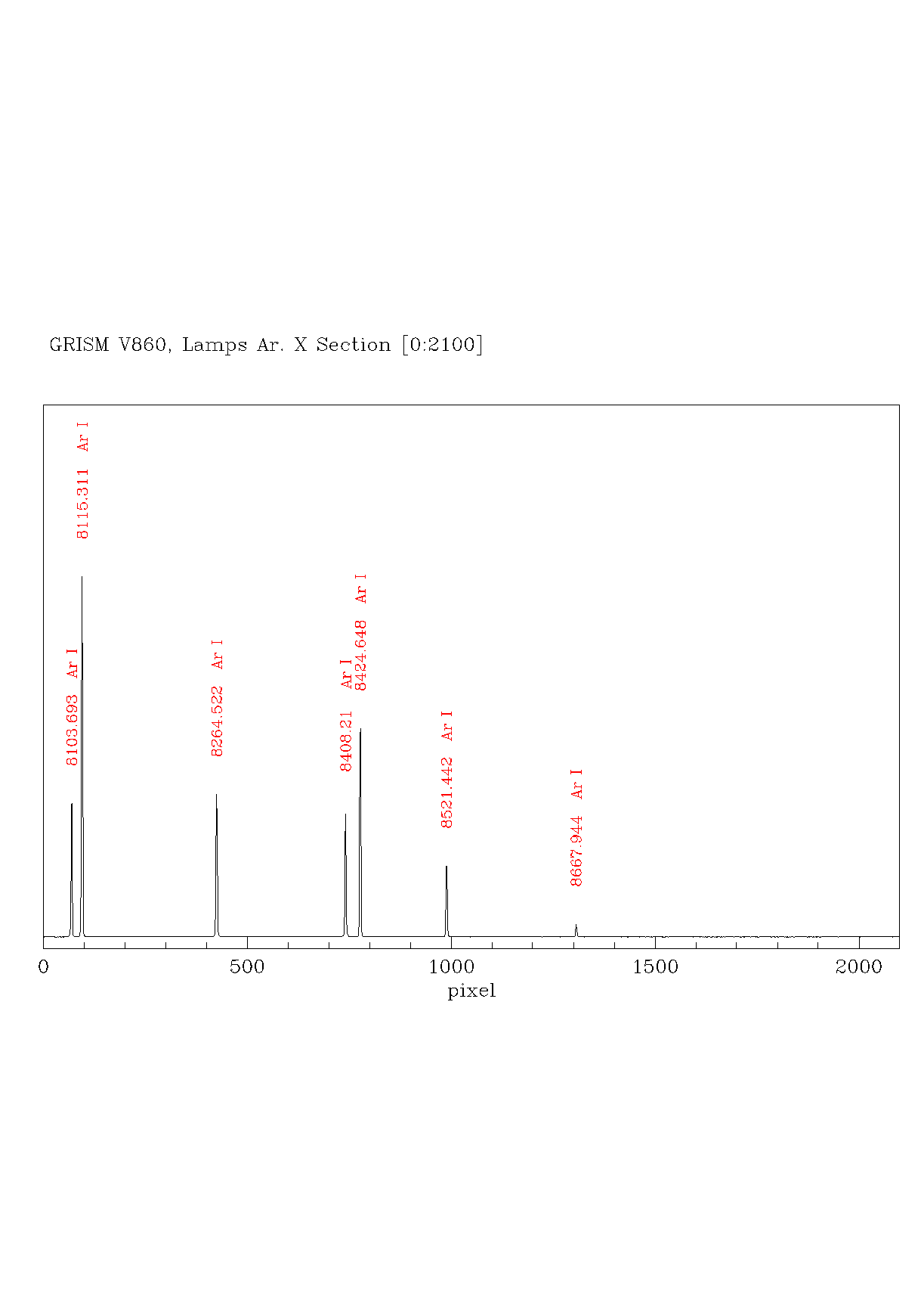
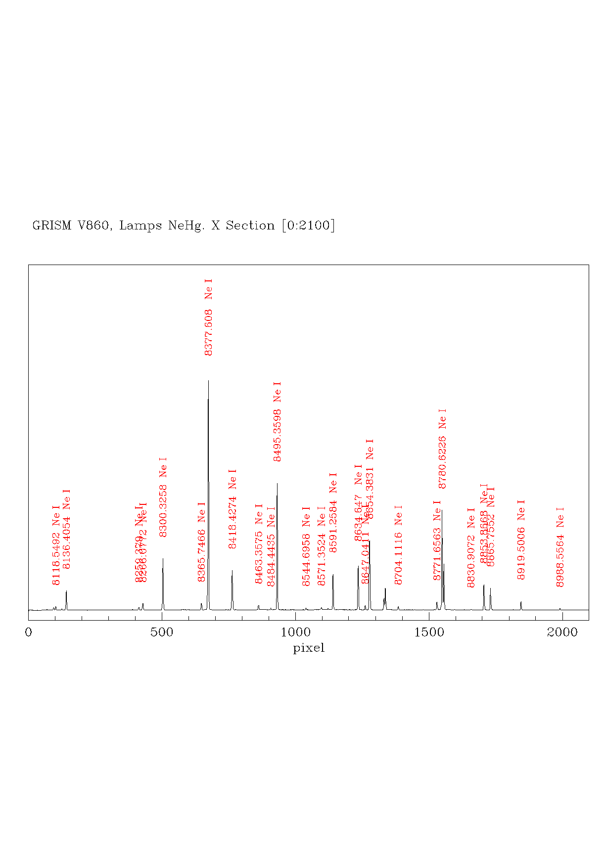
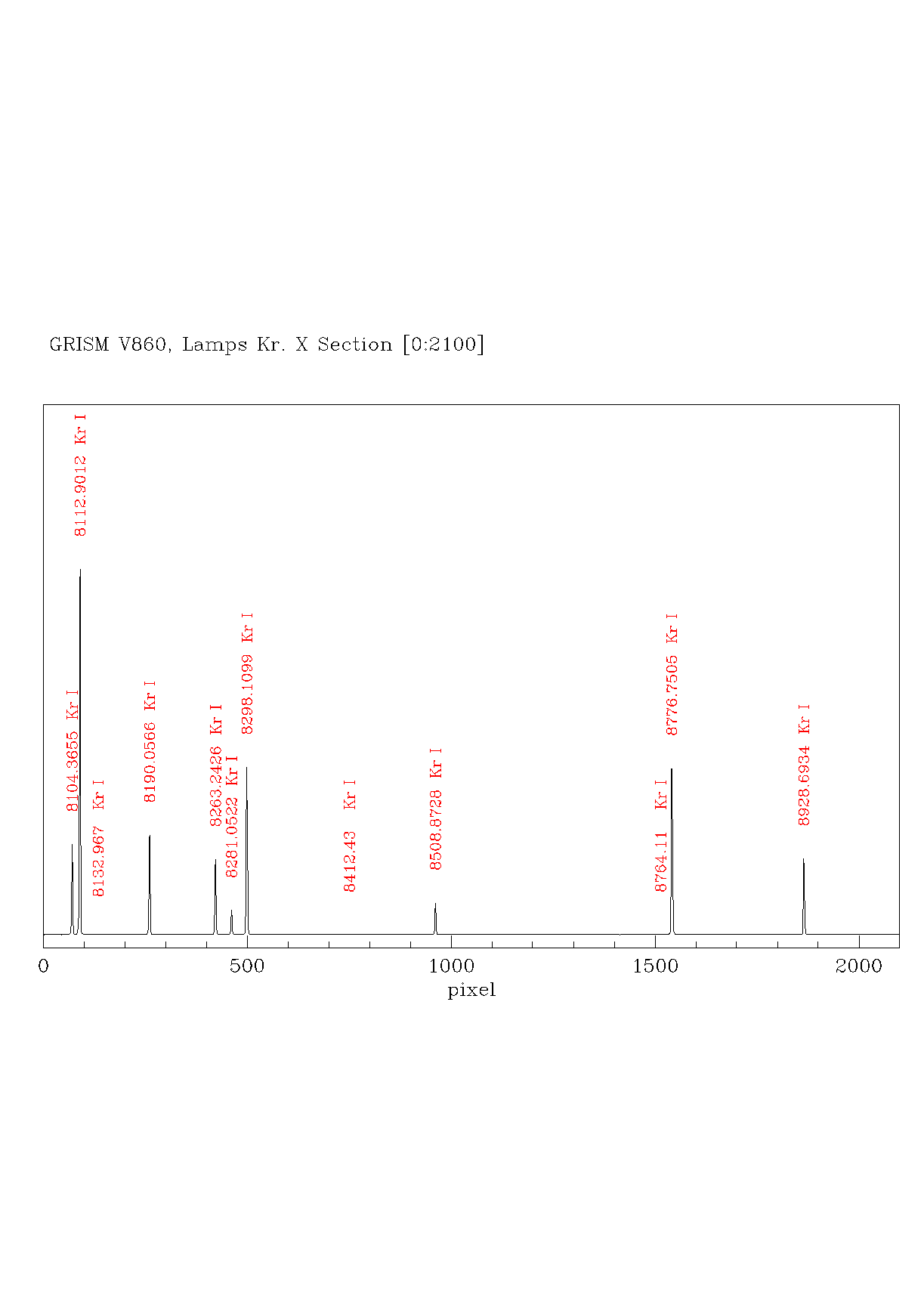
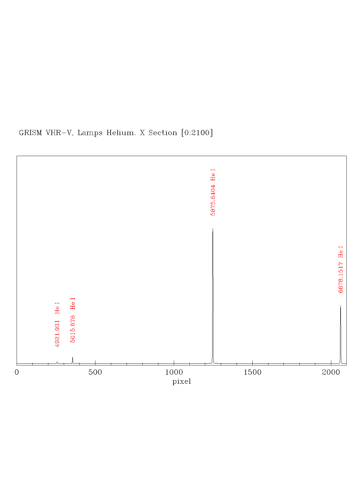
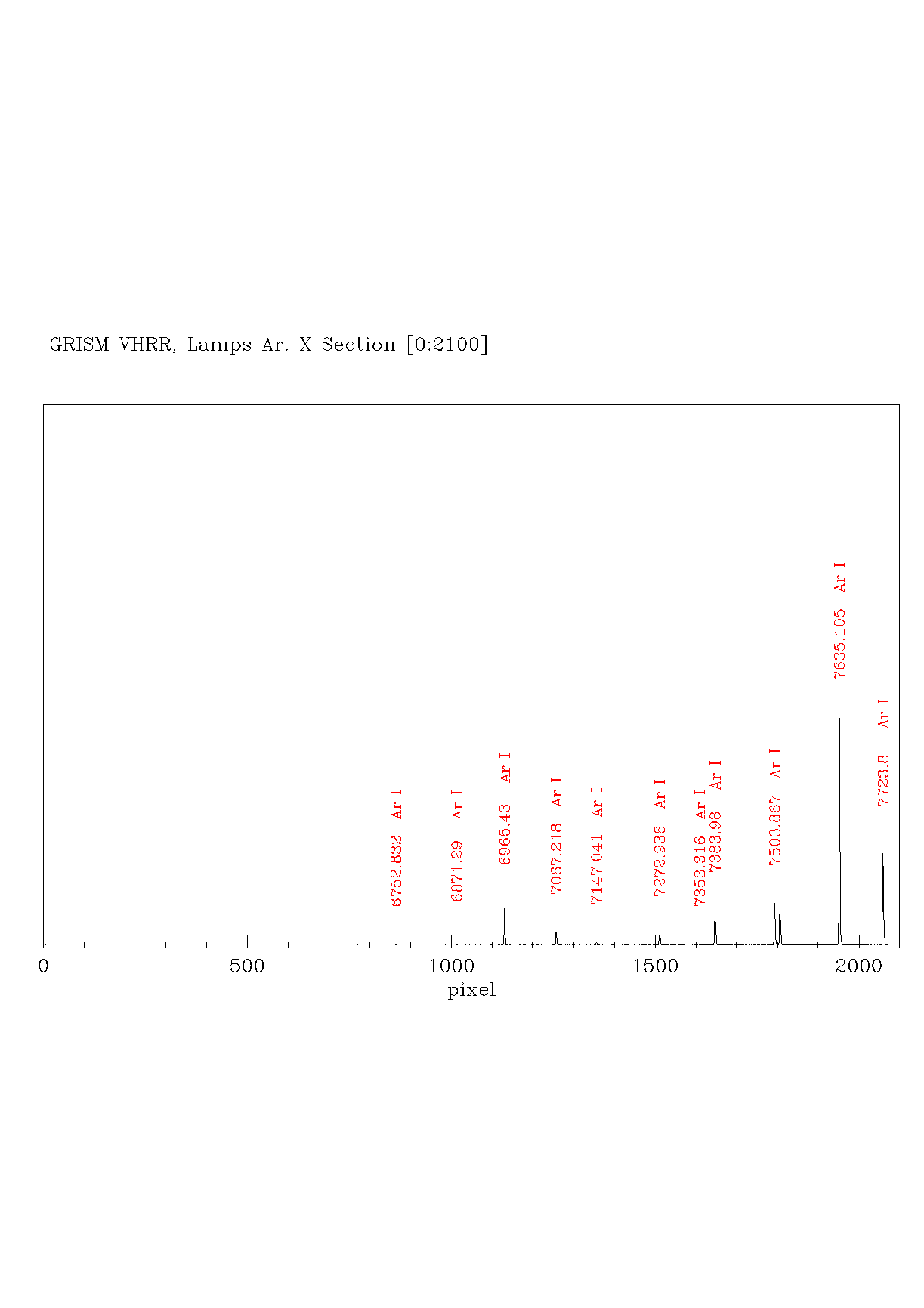
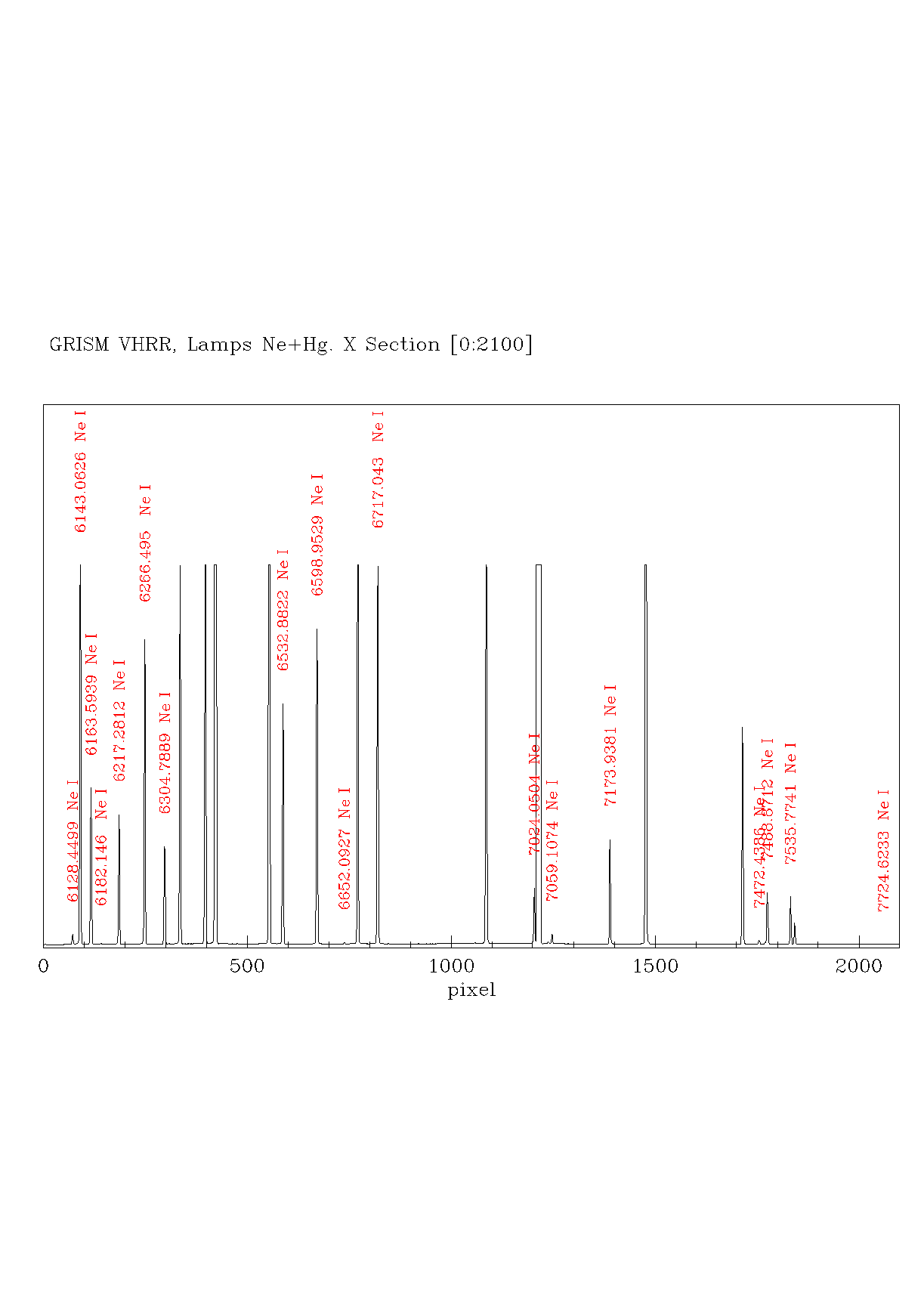
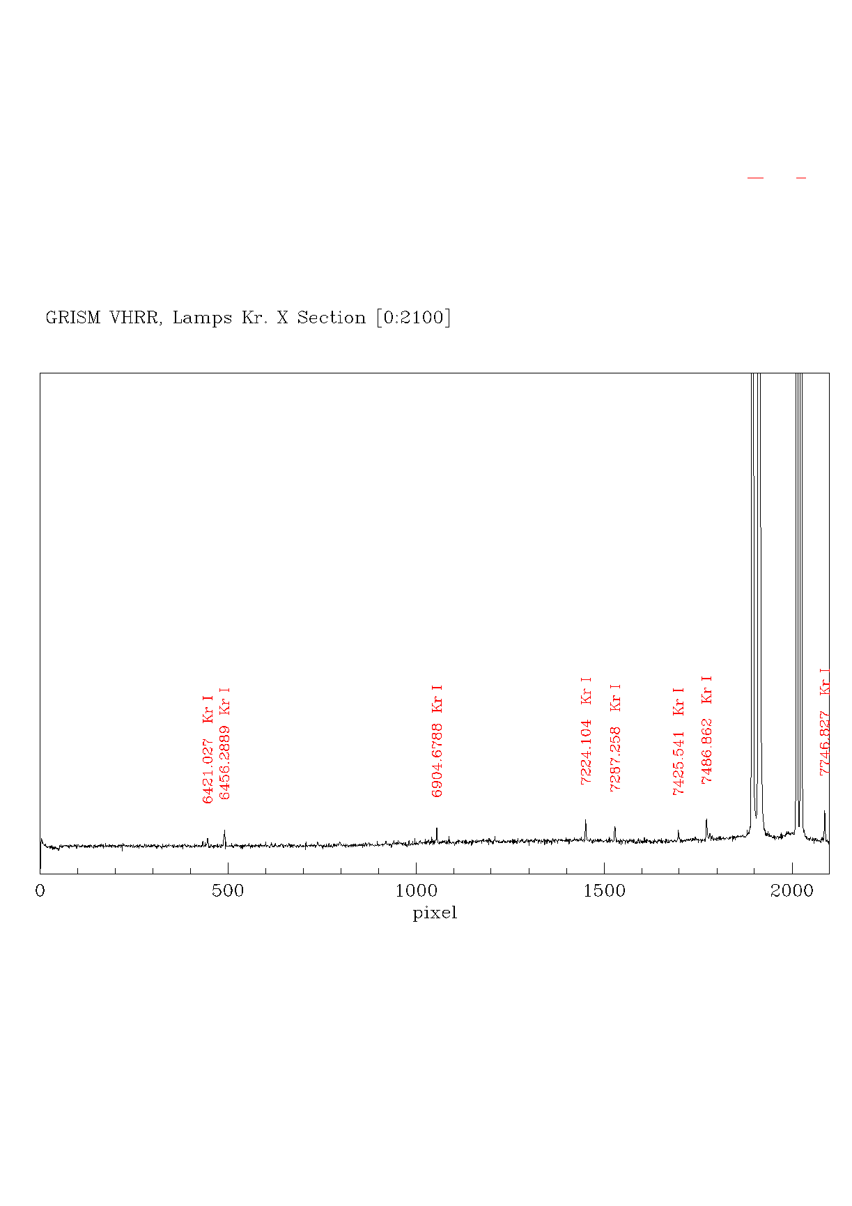
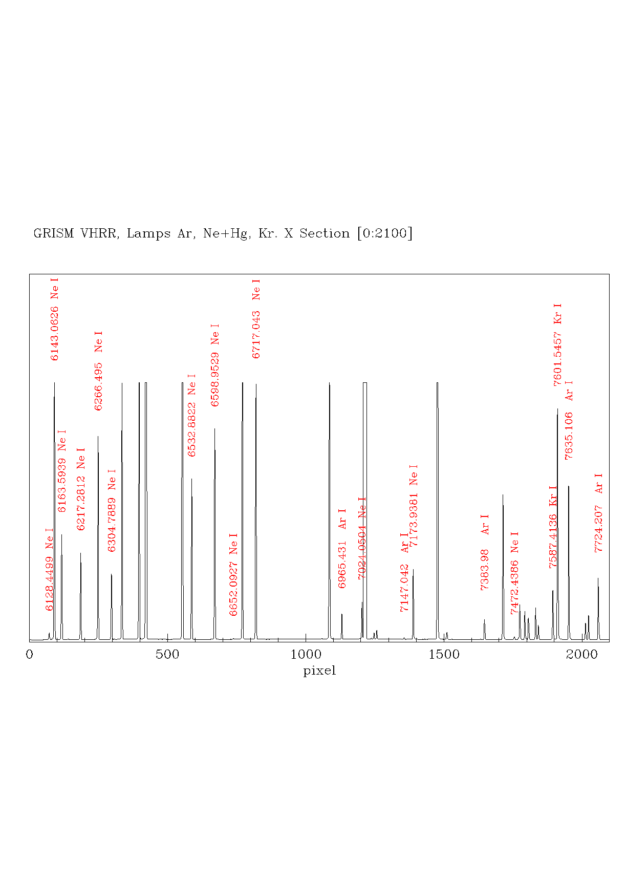
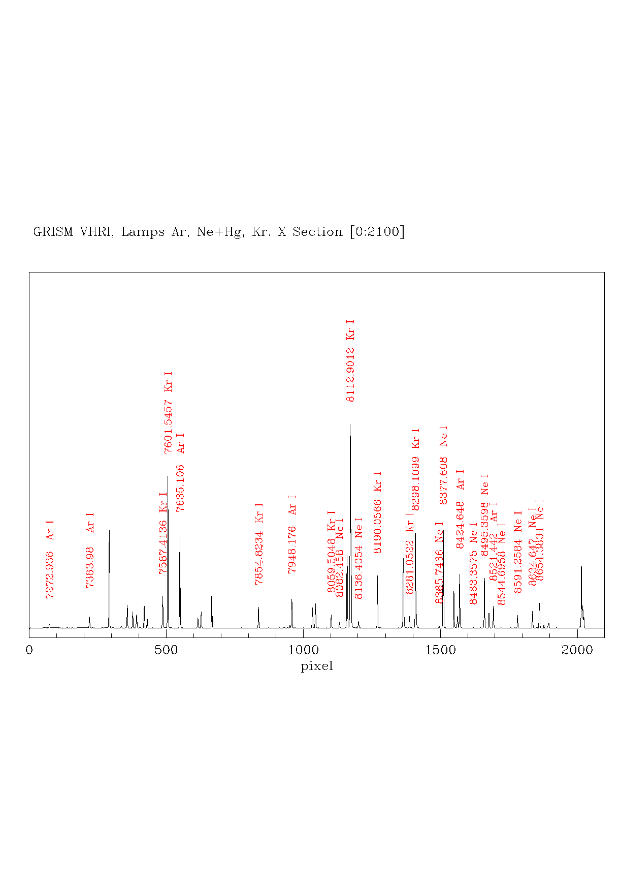
Ar | Ne+Hg | Kr | Ar, Ne+Hg, Kr | Th | He | More |
| LR-B | 2.52 | 3000 | 5850 | 8430 | 585 | yes | yes | yes | yes | no | yes | tar file |
| LR-R(1) | 2.61 | 4470 | 7400 | 10073 | 714 | yes | yes | yes | yes | no | no | tar file |
| V390(2) | 0.26 | 3634 | 3900 | 4166 | 3766 | no | no | no | no | old | no | tar file |
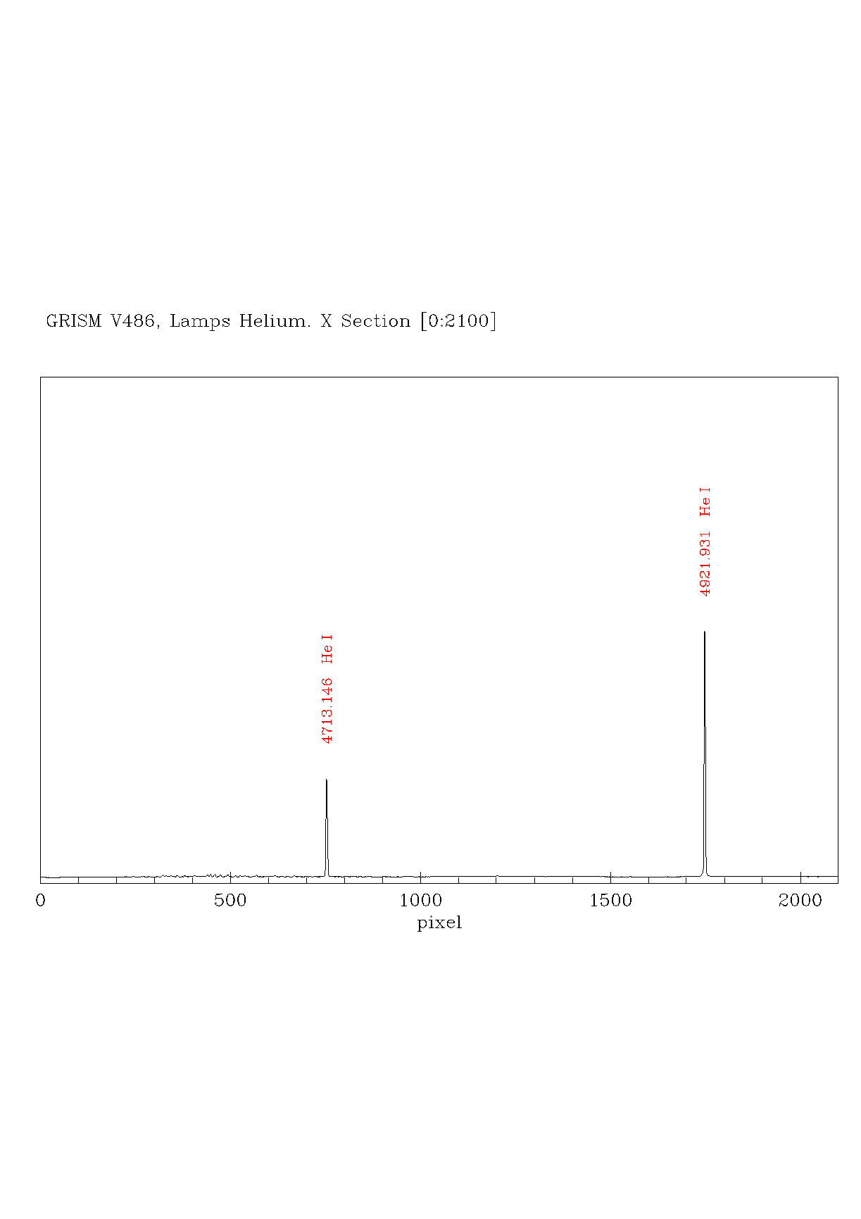
| V486(5) | 0.20 | 4612 | 4725 | 4838 | 5953 | no | no | no | no | no | Yes (Read note #5) | tar file |
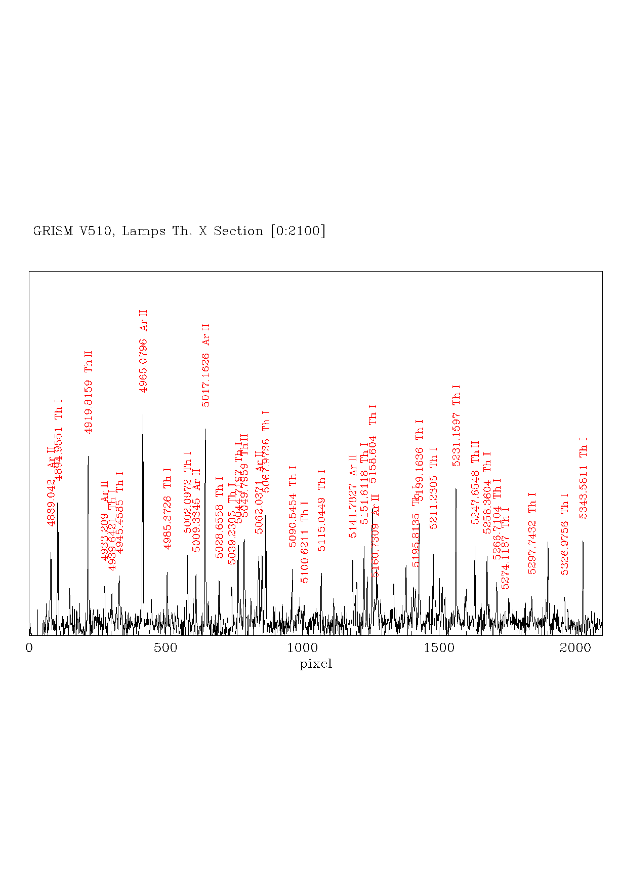
| V510(2) | 0.22 | 4875 | 5100 | 5325 | 5950 | no | no | no | no | yes | no | tar file |
| V589(2) | 0.27 | 5619 | 5895 | 6171 | 5502 | no | old | no | no | no | no | tar file |
| V656 | 0.32 | 6232 | 6560 | 6888 | 5248 | yes | yes | no | yes | no | no | tar file |
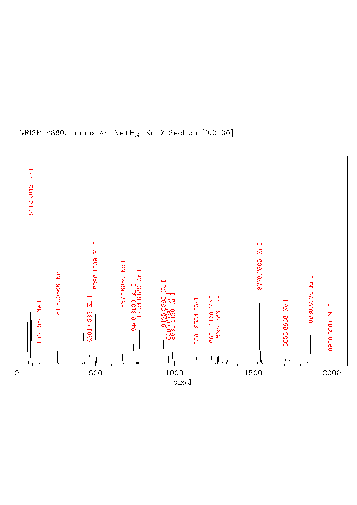
| V860(3) | 0.44 | 8149 | 8600 | 9051 | 4000 | yes | yes | yes | yes | no | no | tar file |
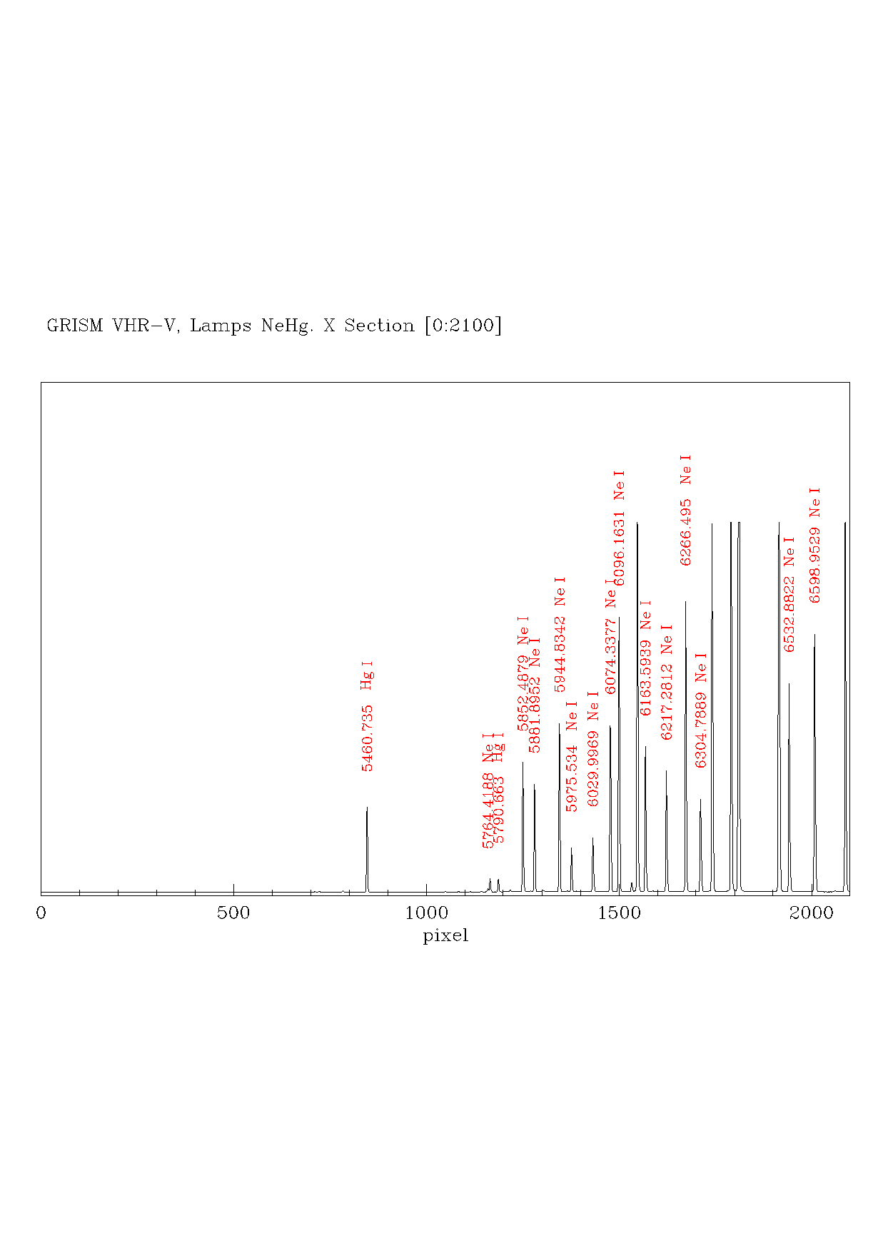
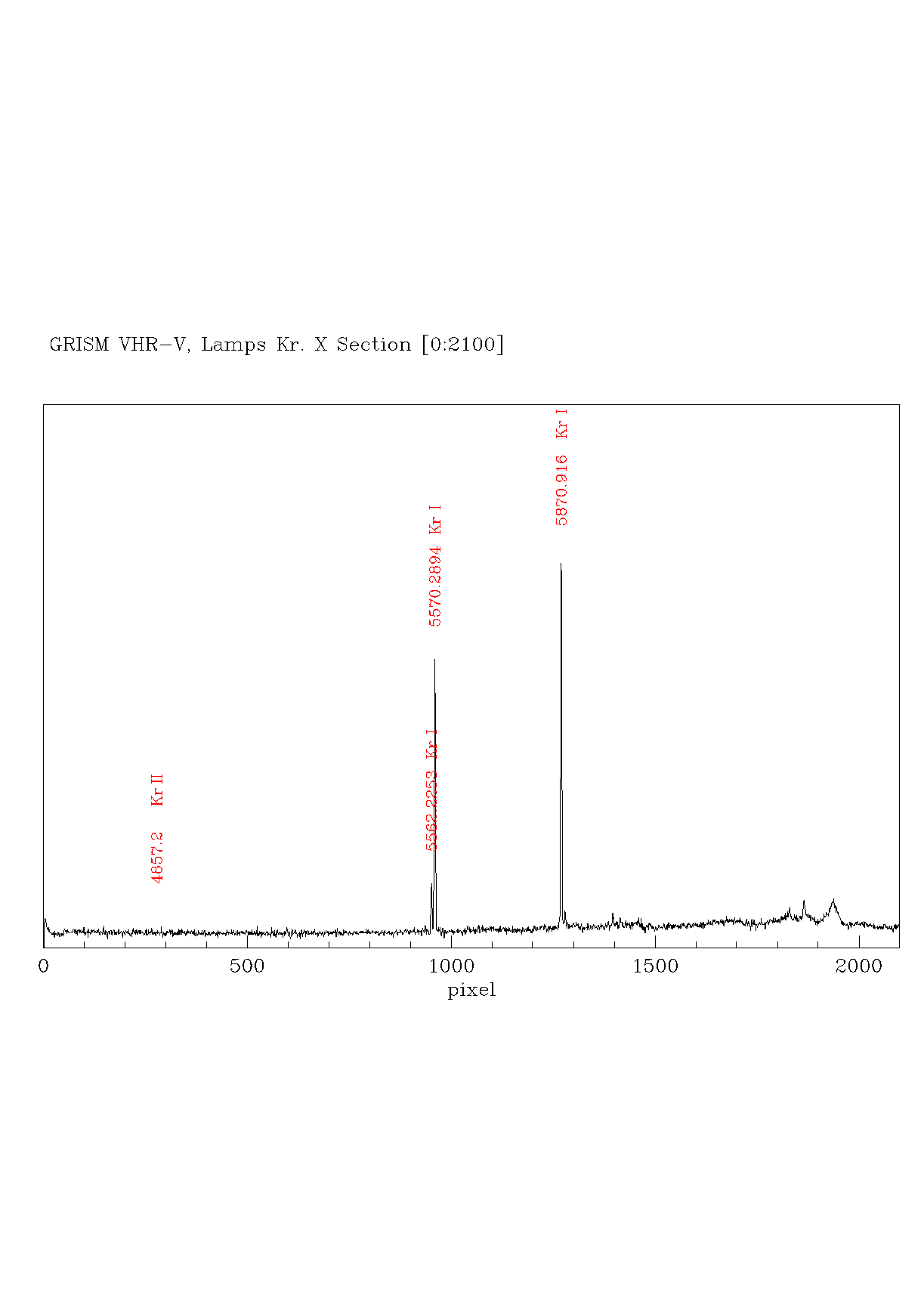
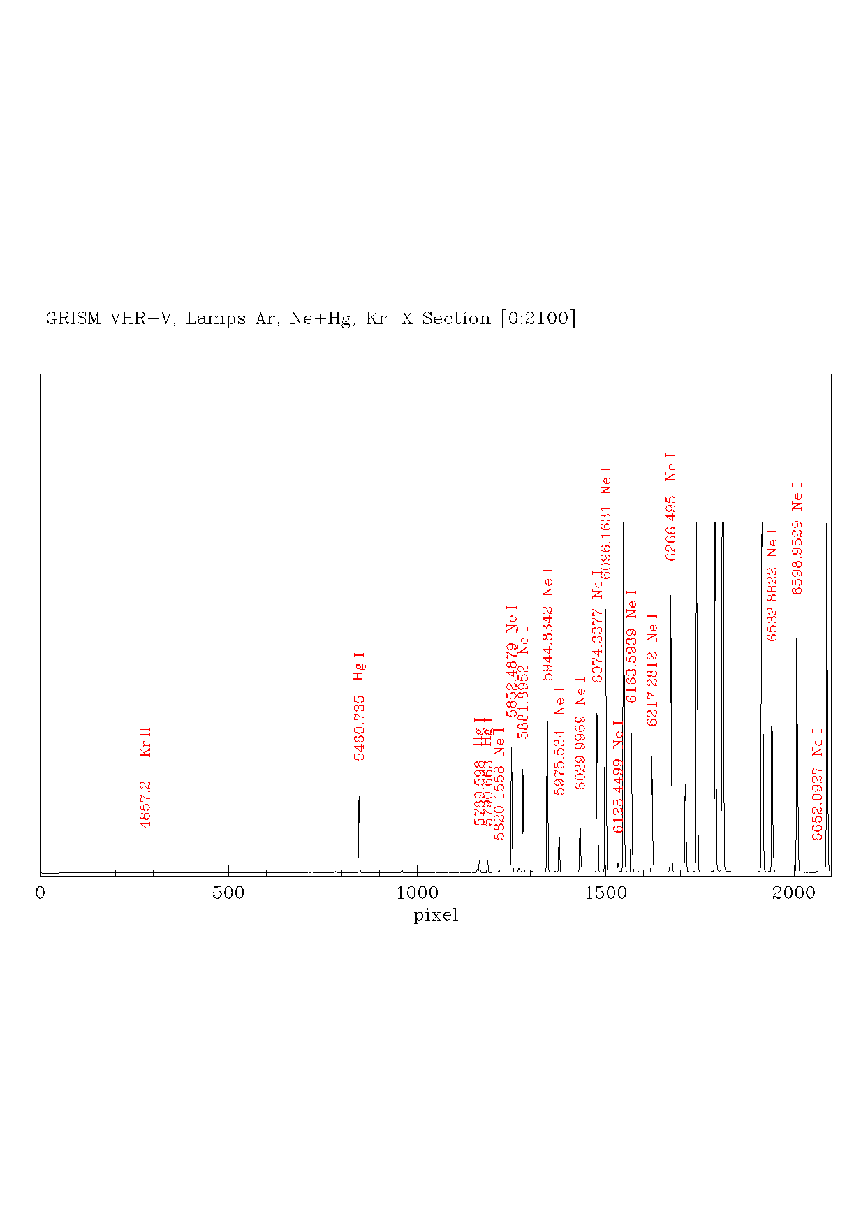
| VHRV | 0.95 | 4752 | 5725 | 6698 | 1527 | no | yes | yes | yes | no | yes | tar file |
| VHRR(3) | 0.70 | 6238 | 7000 | 7717 | 2513 | yes | yes | yes | yes | no | no | tar file |
| VHRI(3) | 0.68 | 7433 | 8130 | 8826 | 3035 | no | no | no | yes | no | no | tar file |
IMPORTANT NOTES:
- The LR-R Grism has a built-in order-blocking filter cutting blueward ~5000 Å; nevertheless, blue objects will show noticeable second-order overlap above ~9500 Å (see Plot).
- This Grism is not mounted on the grism wheel and may be used ONLY in visitor mode. Users interested in using this grism must explicitely request for it in the Observing Proposal.
- This Grisms suffer of significant second-order effect and will be automatically coupled with the ~560 nm cut-on filter available on the filters wheel.
- Resolution calculated for a 1" Slit.
- Please Note that there aren't, at the moment, suitable wavelength calibration lamps for this GRISM.
These grisms will produce a spectrum shifted by about -30" in Y with respect to the position on the target. Please consider it in case of MOS observations (the spectrum of objects too close to the lower border of the mask could fall outside the CCD !)
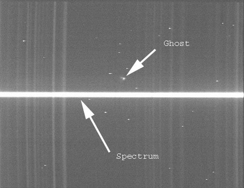
Figure4. The typical ghost which affects almost all the VPH
grisms;
spectrum taken with V656 is shown.
IMPORTANT NOTES:
- The LR-R Grism has a built-in order-blocking filter cutting blueward ~5000 Å; nevertheless, blue objects will show noticeable second-order overlap above ~9500 Å (see Plot).
- This Grism is not mounted on the grism wheel and may be used ONLY in visitor mode. Users interested in using this grism must explicitely request for it in the Observing Proposal.
- This Grisms suffer of significant second-order effect and will be automatically coupled with the ~560 nm cut-on filter available on the filters wheel.
- Resolution calculated for a 1" Slit.
- Please Note that there aren't, at the moment, suitable wavelength calibration lamps for this GRISM.
These grisms will produce a spectrum shifted by about -30" in Y with respect to the position on the target. Please consider it in case of MOS observations (the spectrum of objects too close to the lower border of the mask could fall outside the CCD !)
Figure4. The typical ghost which affects almost all the VPH
grisms;
spectrum taken with V656 is shown.
MOS Spectroscopy
Mask preparation
A MOS mask consists of a number of vertical (along Y)
slits of the same width (either 1.1" or 1.6") and different lengths.
The slit width is set by the drilling tool used (0.2 or 0.3 mm) and
must be clearly specified when the MOS files are submitted.
Slits can be positioned anywhere within a rectangular area of X=6' by
Y=7.7' (sky projected angles) around the mask center. If you
are planning to observe with one of the V390, V589 or V656 GRISM
please read the note under the GRISMS description section.
The relative positions of the slits (positive toward E and N for
position angle=0) must be defined and submitted (see below) by the user
trying to maximize the number (typically 15-25) of objects and avoiding
any overlap of the slits in the Y direction.
To this purpose, any position angle can be adopted when designing the
masks.
The value of position angle of each mask must be comunicated to the
contact
astronomer. It will be of fundamental importance during
observations even if is not needed during the manufacturing
phase. To
simplify the observing procedures we recommend
including in the mask two pinholes (i.e. slits of zero length) centered
on relatively bright (V ~13-15), easily identifiable stars within the
field of view.
Also, consider the possibility to put in your mask three slitlets
(toward the EAST border, center and toward the WEST border)
in order to get clean sky spectra with the widest possible wavelenght
range. This could be useful to better subtract the sky from your
targets spectra. The relative positions of the slits can be determined
from any undistorted image with precisely known scale, ideally with an
accuracy
better than 0.1%.
Images from DOLORES (with any filter) can be used for this purpose, the
scale is 0.252 arcsec/pix and with totally
negligible distortion.
DOLORES images taken at position angle=0 have a standard N-up E-left
orientation.
The resulting slit positions should be arranged into a text file as in
this example .
The files (one per mask) must be then sent to the contact astronomer in
due time (see below).
As an alternative, you may prepare the masks using IMDI,
an IDL interactive program developed and maintained by Enrico Held
(INAF-Padova Observatory) which requires DOLORES (pre)images. The files
produced by this program should be also sent to the contact astronomer.
Each program can request up to a maximum of 5 MASKS per
night and 10 MASKS per observing run.
To make sure that the masks are prepared in time, the observer must
submit the above mentioned files at least 4 WEEKS before his/her
observing run.
Observers requiring pre-imaging must provide all the information for
the pre-imaging at least 2 MONTHS in advance of the scheduled nights
for MOS.
The pre-imaging will be executed as soon as possible in service mode
and the time used will be counted as a part of the total time allocated
to the proposal.
Please note that, in case of long periods of bad
weather, the TNG cannot guarantee that the pre-imaging observations
will be executed.
Decomisioned
Information on decomissioned detectors, filters and grisms are available upon request
SPECTROPHOTOMETRIC STARS
A set of Spectrophotometric stars, extracted from the
IRAF
database and well suited for calibration even with the reddest LRS
Grisms is given in Table 3.
Finding charts are 10'x10' cut-outs from DSS2 Red (North Up, EAST
RIGHT!, just like LRS field orientation).
| Name | Sp. Type | Vmag | R.A. (J2000) | Dec. (J2000) | λ Coverage | Other name |
| Feige24 | DA+M1V | 12.42 | 02 35 07.36 | +03 43 56.9 | 3340-9440 | EG20 |
| HD19445 | sdF | 7.98 | 03 08 25.59 | +26 19 51.4 | 3200-12000 | BD+25 495 |
| G191-B2B | DA0 | 11.85 | 05 05 30.60 | +52 49 56.0 | 3200-10520 | EG247 |
| Hiltner600 | B1V | 10.42 | 06 45 13.40 | +02 08 15.0 | 3300-10100 | |
| HD84937 | sdF | 8.27 | 09 48 56.10 | +13 44 39.3 | 3200-12000 | BD+14 2151 |
| Feige34 | sdO | 11.25 | 10 39 36.70 | +43 06 10.0 | 3200-10200 | EG71 |
| GD140 | DAn | 12.41 | 11 37 05.10 | +29 47 58.0 | 3200-10200 | WD 1134+30 |
| Feige56 | B5p | 11.11 | 12 06 47.19 | +11 40 12.0 | 3300-10100 | HD 105183 |
| Feige66 | sdO | 10.54 | 12 37 23.60 | +25 03 59.0 | 3200-10200 | BD +25 2534 |
| Feige67 | sdO | 11.89 | 12 41 51.80 | +17 31 21.0 | 3200-10200 | BD +18 2647 |
| HZ44 | sdO | 11.66 | 13 23 35.37 | +36 08 0.0 | 3200-10200 | WD 1321+36 |
| GRW+70 5824 | DA | 12.79 | 13 38 50.47 | +70 17 07.6 | 3200-10200 | EG102 |
| BD+262606 | sdF | 9.66 | 14 49 02.31 | +25 42 28.0 | 3080-12000 | LTT 14382 |
| Wolf1346 | DA | 11.59 | 20 34 21.90 | +25 03 51.0 | 3200-10640 | WD 2032+248 |
| BD+284211 | sdOp | 10.56 | 21 51 11.02 | +28 51 50.4 | 3200-10200 | WD 2148+286 |
| BD+174708 | sdF | 9.41 | 22 11 29.54 | +18 05 31.6 | 3200-12000 | LTT 16493 |
| Feige110 | DOp | 11.88 | 23 19 58.40 | -05 09 57.0 | 3300-9950 | EG158 |
Tools for Observations
- Astronomical Daily Almanac for Major Observatories
- On-line Landolt Catalog.
- On-Line Digital Sky Survey
- On-line USNO A-2.0 Astrometric Catalog
For any comments please contact Luca Di Fabrizio.